Investigation of the Possibility for Development of a Fast-Acting Capacitor Bank Based on Controlled Switching
Investigation of the Possibility for Development of a Fast-Acting Capacitor Bank Based on Controlled Switching
Investigation of the Possibility for Development of a Fast-Acting Capacitor Bank Based on Controlled Switching
Dmitry E. Shevtsov,
Dmitry A. Pavlyuchenko,
Novosibirsk State Technical University, Novosibirsk, Russia
Abstract – The paper presents investigations of transients at uncontrolled and controlled switching of a capacitor bank by a vacuum circuit breaker. It is shown that the use of controlled switching allows reducing transient currents and voltages to the values being sufficient for implementation of a fast-acting capacitor bank.
Index Terms – Controlled switching, transients, overvoltages, inrush current, capacitor bank.
I. INTRODUCTION
Reactive power compensation is one of efficient methods of electric energy saving and maintaining the required voltage level in the electrical network.
A reliable, simple and cheap method of compensation is application of cosine capacitor banks. However, fast response of these devices is limited by generation of overvoltages and inrush currents at switchings [1-4], thus these devices cannot be used in the case of abruptly variable load.
In this case, static thyristor controlled VAR compensators having a number of drawbacks are used. The main drawback is a high price.
The present paper proposes the use of controlled switching for development of a fast-acting capacitor bank with saving all its advantages and eliminating the main drawback.
Controlled (or synchronous) switching is a type of switching in the electrical network at the definite time instant that is done with consideration of network operating conditions at the moment of switching, and that allows performing closing and opening operations at the most propitious moment for power equipment [5-8]. A switching device implementing the principles of controlled switching (controlled circuit breaker) is the device, in which contacts are opened at the given current phase and (or) closed at the given voltage phase [9,10].
Investigations on the problem of controlled switching for limitation of overvoltages and inrush currents have been carried out since the mid-twentieth century [9,11,12]. The greatest contribution to the study of controlled switching of high-voltage circuit breakers was made by the Working Group WG 13.07 (A3.07) CIGRE «Controlled Switching of HVAC Circuit-Breakers», which was specially formed for this purpose [6,7,13-16].
Development and implementation of controlled switching devices are performed in Russia and all over the world. According to CIGRE information for the period from 1984 to 2001, the number of circuit breakers with controlled switching is 2500 pc. 64% of them are intended for switching capacitor banks, 17% – for switching shunting reactors, 17% – for energization of power transformers, and 2% – for energization of transmission lines without high inrush currents and overvoltage levels. In addition, some investigations on the possibility of switching other elements of the electrical network are carried out [17].
The use of controlled switching for reactive elements in electrical networks prevents occurrence of inrush currents and overvoltage generation, increases the switching life time of circuit breakers. Under normal operating conditions, controlled closing of a reactive load by a circuit breaker allows minimizing inrush currents considerably, while controlled opening reduces the probability for restrikes and, as a consequence, overvoltage generation. Controlled switching of normal operating currents also allows improving the following circuit breaker characteristics: enhancement of its switching life time, increase of nominal voltage due to reduction of switching overvoltages [5-7,10, 13-18].
II. PROBLEM DEFINITION
Capacitor banks cannot be used in the case of abruptly variable load because fast response of these devices is limited by generation of overvoltages and inrush currents at switchings.
Capacitor bank opening is performed with generation of high overvoltages in the case of emergency restrikes in a circuit breaker [1]. The probability for occurrence of restrikes during opening of a capacitor bank is of the highest value for oil circuit breakers [2]. As for vacuum circuit breakers, the probability for arc reignition is of the lowest value, that is caused by the fast growth of dielectric strength at contact separation [3].
An inrush current, which is 5...30 times greater than the rated current of a capacitor bank, may be observed at closing of a high-voltage capacitor bank [1,2,4]. Energization of a capacitor bank in addition to the operated capacitor bank without any current-limiting devices causes still greater transient currents. In this case, overvoltage levels do not exceed 2·Uphm. The presence of residual charge at a capacitor at the closing instant provides the increase of inrush currents and overvoltages.
III. PROPOSED MODELES
Investigations on the study of switching processes, analysis of efficiency and determination of application areas for capacitor bank controlled switching require the development of special simulation models. The models were developed in Matlab/Simulink [19], which allows modeling complex power systems using methods of simulation and structural modeling.
A. Model of a Controlled Circuit Breaker
The most important characteristics of vacuum circuit breakers for adequate switching transient simulation in the electrical network are the following: the value of current chopping before the natural zero crossing (4 – 6 A), the change of dielectric strength of a contact gap (determined by a linear characteristic, having the rate of change of 20 – 80 kV/ms), the maximum rate of interrupting current at zero crossing (40 – 160 A/µs), and nonsimultaneous contact operation (not more than 0.5 ms).
Determination of nonsimultaneous contact operation of a circuit breaker was performed by experimental investigations of pole operating time scattering for the controlled vacuum circuit breaker EX-BBC SMARTIC 6(10)-20/1000 [20,23] at the laboratory of Power Engineering Institute of National Research Tomsk Polytechnic University. Other characteristics of vacuum circuit breakers were determined from publications [3,21,22].
Fig. 1 shows the structure diagrams of processes at circuit breaker opening and closing [20]. After sending a command for opening, circuit breaker contacts begin separating (Fig. 1, a). The first electrical arc extinction is possible at flowing of current i, which value is not greater than chopping current Ichop. Dielectric strength of a contact gap uDS is increasing after the beginning of contact opening. In the case of insufficient dielectric strength between circuit breaker contacts, arc reignition occurs. An electric arc is extinguished if the rate of high-frequency current zero crossing di/dt is not greater than the given current rate (di/dt)max, at which current chopping is possible. Arc extinction is also possible in the case of virtual current chopping. The processes of arc ignition and arc extinction may repeat several times until the dielectric strength of a contact gap is lower than the recovery voltage between contacts uR.
Then, we consider the process of circuit breaker closing (Fig. 1, b). After sending a command for closing, circuit breaker contacts begin approaching. In this case, dielectric strength of a contact gap uDS is decreasing. At the instant, when the contact voltage uR exceeds the dielectric strength of a contact gap, prestrike, or arc ignition, is observed. Conditions, at which arc extinction is possible, are similar to conditions of circuit breaker opening considered above. These processes (i.e. arc ignition and arc extinction) occur before the instant of contact touching in a circuit breaker.

B. Model of a Power Supply Source
As a power supply source, the block Three-Phase Source was chosen [19]. This block consists of three sources of alternating voltage, which are wye-connected with or without a neutral conductor. Each phase of the source has internal resistance and inductive reactance. Internal impedances are identical for all phases. The source internal impedance can be given directly by values of resistance and inductance, or indirectly by short circuit parameters.
The block Three-Phase Source does not include phase-to-ground and phase-to-phase capacitances. To take into account these parameters, the standard block Three-Phase Parallel RLC Branch can be used.
C. Model of a Cable Line
The model of a cable line is developed using the block Distributed Parameters Line, which represents a three-phase transmission line with distributed parameters [24]. The block Distributed Parameters Line includes line resistances, inductances and capacitances of the positive sequence and the zero sequence. Resistance and inductive reactance of the positive sequence can be determined by reference data [25]. Zero-sequence parameters can be calculated using the following expressions [26,27]:
![]()
where r1, x1 – positive-sequence resistance and inductive reactance; r0, x0 – zero-sequence resistance and inductive reactance.
Zero-sequence capacitance can be determined by reference data [25]. To find a positive-sequence capacitance, it is necessary to have a phase-to-phase capacitance determined by the expression [25]:
![]()
where Cph-ph – phase-to-phase capacitance; C0 – zero-sequence capacitance.
Then, a positive-sequence capacitance can be calculated by the following equation [27]:
![]()
D. Model of a Capacitor Bank
A capacitor bank was modeled by the standard block Three-Phase Parallel RLC Load. This block represents a three-phase circuit consisting of three parallel-connected elements: resistor, inductor and capacitor. Parameters of the circuit are given by a three-phase load power (or individually for each phase) at the rated voltage and frequency. The block has the possibility of choosing an element connection configuration (delta, wye) and neutral grounding conditions.
According to [28], capacitor units with the voltage above 1 kV should be equipped with discharge devices, such as voltage transformers or devices having the impedance of resistance and inductive reactance. Parameters of a discharge device can be calculated using the methodology given in [29].
Three-phase power for the block Three-Phase Parallel RLC Load can be determined by the following expressions:

where P, QL – active and reactive power of a discharge device; QC – reactive power of a capacitor; ω – angular frequency; U – phase voltage of a capacitor unit.
The general view of the 6 (10) kV electrical network model for investigations of switching transients of a capacitive load is presented in Fig. 2. Results obtain from the proposed model have a good coincidence with experimental results given in several publications [1-3].

Fig. 2. Model of the 6 kV electrical network: Cph, Cph-ph – phase and phase-to-phase capacitances of the source.
IV. SIMULATION RESULTS AND DISCUSSIONS
A. Interruption of a Capacitor Bank
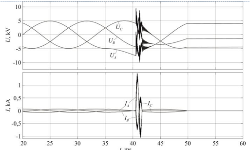
As was noted above, capacitor bank opening is performed without restrikes in a circuit breaker and without generation of dangerous overvoltage levels. The highest values are observed at switching of the first circuit breaker phase being equal to not more than 2·Uphm at the interrupted phase and not more than 3·Uphm between circuit breaker contacts. This fact is illustrated in Fig. 3.
Interruption of a capacitor unit under natural sequence of phase current zero crossings slightly decreases overvoltage levels. In this case, voltage at the first interrupted phase is equal to 1.5·Uphm (Fig. 4).
Arc reignitions at capacitor bank opening are possible to occur at sufficiently low rate of rise of electric strength of separating circuit breaker contacts. Voltages and currents with arc reignitions in the first interrupted phase are presented in Fig. 5. In this case, a contact gap is characterized by low dielectric strength at the first instant after current interruption, because the instant of the beginning of contact moving is close to the instant of occurrence of the chopping current, and the dielectric strength recovery rate is equal to 1.5 kV/ms. For modern vacuum circuit breakers, the probability for arc reignitions is very low that is caused by the fast rise of electric strength of a contact gap (k = 20 – 80 kV/ms [3,21,22]).
Therefore, for the decrease of overvoltage levels and elimination of the conditions for occurrence of arc reignitions, it is reasonable to disconnect a capacitor bank using the А-ВС switching algorithm: interruption is realized before the instant of current zero crossing in phases that corresponds to the following time parameters: TA = 33 ms, TB = TC = 38 ms (Fig. 4). In this case, scattering of instants for each circuit breaker pole operation may be equal not more than 2 ms.
B. Energization of a Capacitor Bank
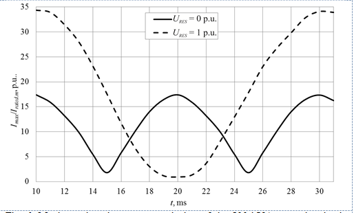
In 6 (10) kV electrical networks in Russia, capacitor banks are operated with an ungrounded neutral, therefore transient process occurs only at contact closing of at least two circuit breaker poles. Fig. 6 presents the simulation results of simultaneous closing of first two phases of the 500 kVAr capacitor bank, operated with an ungrounded neutral, at different values of residual voltage with variation of a switching instant.

Fig. 3. Interruption of one phase of the 500 kVAr capacitor bank: UR – voltage between circuit breaker contacts.

Fig. 4. Interruption of three phases of the 500 kVAr capacitor bank.

Fig. 5. Interruption of the 500 kVAr capacitor bank with arc reignitions in the phase A.

Fig. 6. Maximum inrush currents at closing of the 500 kVAr capacitor bank at different values of residual voltage.
Fig. 6 validates the dependence of the inrush current amplitude of the capacitor bank on the instant of closing and the presence of the residual charge. The condition for occurrence of the maximum transient current is capacitor bank closing at the certain instant Tcl (Fig. 7) corresponding to the maximum voltage difference at the circuit breaker from the system side (Us) and the load side, i.e. residual voltage of the capacitor bank (Ures). If residual voltage exists at the capacitor, the maximum inrush current may be two times greater (Fig. 6).

Fig. 7. Voltages at capacitor bank energization: Us – voltage at the circuit breaker from the system side; Ures – voltage at the circuit breaker from the load side; Uresult – resulting voltage after circuit breaker closing at the instant Tcl.
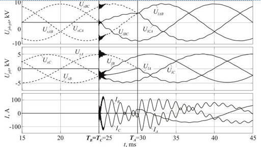
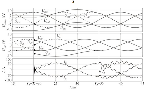
Fig. 6 also shows that there are instants, at which minimal inrush currents are observed at capacitor bank closing. Based on conducted investigations, an optimal algorithm for energization of the capacitor bank wye-connected with an ungrounded neutral is the СВ-А algorithm. In this case, it is necessary to perform simultaneous closing of two capacitor bank phases at the instant of equality of phase-to-phase voltages between these phases of the circuit breaker from the system side and the load side. Then, switching of the third phase should be done at the instant of equality of corresponding voltages of the switched phase of the circuit breaker. Fig. 8 illustrates voltages and currents at capacitor unit energization with and without residual charge according to the proposed switching algorithm. Capacitor bank energization without residual charge is realized at instants of corresponding voltage zero crossings, that is TС = TВ = 25 ms, TА = 30 ms (Fig. 8, a). In the presence of residual charge, capacitor bank energization is performed at the instants of equality of voltages from the system side and the load side, that corresponds to TС = TВ = 20 ms, TА = 35 ms (Fig. 8, b).
Determination of permissible scattering of operating times for circuit breaker poles at capacitor bank energization involves finding a time interval, in which the given inrush current is not exceeded. Calculation values of permissible scattering at various values of the maximum transient current are presented in Fig. 9. Capacitor bank energization using the СВ-А algorithm allows reducing inrush currents to the values of not more than 3·Irated.m with the accuracy of operation being not more than 0.9 ms for first two poles, and 0.6 ms for the third pole.

а)

The use of controlled switching algorithms allows reducing inrush currents at capacitor bank energization considerably with and without residual charge. It makes possible to perform reclosing just after interruption, without any time delay for capacitor discharge. It allows, in turn, developing a fast-acting reactive power compensator based on controlled switching.
V. CONCLUSION
Capacitor bank interruption by modern vacuum circuit breakers having high rates of rise of dielectric strength (more than 20 kV/ms) is characterized by the low probability for arc reignitions.
To decrease overvoltage levels and eliminate the probability for arc reignitions, it is reasonable to disconnect a capacitor bank using the А-ВС switching algorithm: disconnection is realized before the instant of current zero crossing in phases that corresponds to the following time parameters: TA = 33 ms, TB = TC = 38 ms. In this case, scattering of instants for each circuit breaker pole operation may be equal not more than 2 ms.
The main factors influencing on inrush current amplitudes at capacitor bank energization are residual charge at the capacitor and the instant of contacts closing of the circuit breaker. The maximum inrush current is observed at energization of the capacitor bank having the highest residual charge at the instant of maximum voltage difference from the system side and the load side.
The optimal algorithm for capacitor unit energization is the СВ-А algorithm. In this case, it is necessary to perform simultaneous closing of two capacitor bank phases at the instant of equality of phase-to-phase voltages between these phases of the circuit breaker from the system side and the load side. Then, switching of the third phase should be done at the instant of equality of corresponding voltages of the switched phase of the circuit breaker. Capacitor bank energization without residual charge is realized at instants of corresponding voltage zero crossings, that is TС = TВ = 25 ms, TА = 30 ms. Capacitor bank energization using the СВ-А algorithm allows reducing inrush currents to the values of not more than 3·Irated.m with the accuracy of circuit breaker pole operation of not worse than 0.6 ms.
The use of controlled switching for capacitor banks allows performing reclosing just after interruption, without any time delay for capacitor discharge. It allows, in turn, developing a fast-acting reactive power compensator based on controlled switching.
REFERENCES
[1] H. Nishikawa, K. Yokokura, S. Matsuda, M. Okawa, H. Koike, T. Kato. A method of evaluating a circuit breaker for a capacitor bank and suppression of restriking overvoltages // IEEE Transactions on power apparatus and systems, 1983. V. PAS-102. No. 6. pp. 1574-1581.
[2] Working group 13.04. Shunt capacitor bank switching stresses and test methods (1st part) // Electra, 1999. No. 182. pp.165-189.
[3] G.A. Evdokunin, A.A. Korepanov. Overvoltages at vacuum circuit breaker switchings and overvoltage suppression // Electricity, 1998. № 4. pp. 2-14 (in Russian).
[4] L.M. Smith. A practical approach in substation capacitor bank applications to calculating, limiting and reducing the effects of transient currents // IEEE Transactions on industry applications, 1995. V. 31. iss. 4. pp. 721-724.
[5] D. Goldsworthy, T. Roseburg, D. Tziouvaras, J. Pope. Controlled switching of HVAC circuit breakers: application examples and benefits // 61st annual conference for protective relay engineers, April 2008. No. 197. pp. 520-535.
[6] Working group 13.07. Controlled switching of HVAC circuit-breakers: guide for application lines, reactors, capacitors, transformers (first part) // Electra, 1999. No. 183. pp. 43-73.
[7] Working group 13.07. Controlled switching of HVAC circuit-breakers: guide for application lines, reactors, capacitors, transformers (2nd part) // Electra, 1999. No. 185. pp. 37-57.
[8] D.A. Pavlyuchenko, A.A. Achitaev, D.E. Shevtsov. Controlled switching for a group of induction motors // 2 International conference on industrial engineering, applications and manufacturing (ICIEAM), Russian, Chelyabinsk, 19-20 May 2016. IEEE, 2016. Art. 3.6. pp. 1-6. DOI: 10.1109/ICIEAM.2016.7911452.
[9] L.G. Kleparskaya. Controlled Circuit Breakers // Moscow: Energiya, 1973. p. 112 (in Russian).
[10] S. Kokin, D. Pavlyuchenko, D. Shevtsov. Features of controlled switching under normal and emergency operating conditions in medium voltage networks // 18th international scientific conference on electric power engineering (EPE), Kouty nad Desnou, Czech Republic, 17-19 May 2017. IEEE, 2017. pp. 1-5. DOI: 10.1109/EPE.2017.7967232.
[11] G.V. Butkevich, L.G. Kleparskaya, V.F. Nabatov. Maximum permissible time of contact separation of air circuit breakers for controlled switching // Electricity, 1969. № 8, pp. 67-67 (in Russian).
[12] K.P. Kadomskaya, E.S. Nesgovorov, L.V. Petrakova, V.S. Ponomarev. Suppression of internal overvoltages using control of switching instants of circuit breakers // Electricity, 1969. № 9, pp. 10-13 (in Russian).
[13] Working group 13.07. Controlled switching of HVAC circuit breakers: planning, specification and tasting of controlled switching systems // Electra, 2001. No. 197. pp. 23-33.
[14] Working group 13.07. Controlled switching of HVAC circuit-breakers – benefits and economic aspects // CIGRE Technical Brochure, 2004. No. 262. p.34.
[15] Working group 13.07. Controlled Switching of HVAC circuit-breakers – guidance for further applications including unloaded transformer switching, load and fault interruption and curcuit-breaker uprating // CIGRE Technical Brochure, 2004. No. 263. p. 56.
[16] Working group 13.07. Controlled Switching of HVAC circuit-breakers – planning, specification and testing of controlled switching systems // CIGRE Technical Brochure, 2004. No. 264. p.56.
[17] G.S. Belkin. Application of self-controlled apparatus (“intelligent” apparatus) for switching operations in high voltage networks // Electrical Engineering, 2005. № 12. pp. 3-9 (in Russian).
[18] E. Andersen, S. Berneryd, S. Lidahl. Synchronous energizing of shunt reactors and shunt capacitors // SIGRE Rep, 1988. No. 13-12.
[19] I.V. Chernykh. Simulation of electrotechnical devices in MATLAB. SimPowerSystems and Simulink // Textbook, Moscow: DMK Press, 2007. p. 288 (in Russian).
[20] D.A. Pavlyuchenko, D.E. Shevtsov Controlled Vacuum 6 (10) kV Circuit Breaker Model // The 11th international forum on strategic technology (IFOST 2016), Russian, Novosibirsk, 1-3 July 2016. IEEE, 2017. V. 2. pp. 177-182. DOI: 10.1109/IFOST.2016.7884221.
[21] A.V. Ivanov, I.L. Degtyarev. Theoretical and experimental investigations on electrophysical processes and characteristics of vacuum interrupter at motor switchings // Ufa: Oil and Gas Engineering, 2007. № 1. pp. 1-10 (in Russian).
[22] K.P. Kadomskaya, R.V. Kopylov. Requirements to a vacuum interrupter and special measures for reliable interruption of locked motors // Power Stations Journal, 2002. № 9. pp. 56-60 (in Russian).
[23] A.A. Achitaev, D.A. Pavlyuchenko, E.V. Prokhorenko, D.E. Shevtsov. Using a controlled vacuum circuit breaker in urban electrical networks // Glavny Energetik Journal, 2014. № 7, pp. 46-52 (in Russian).
[24] H.W. Dommel. Digital computer solution of electromagnetic transients in single and multiple networks // IEEE Transactions on Power Apparatus and Systems, 1969. V. PAS#88. Iss. 4. pp. 388-399.
[25] Handbook of high-voltage electrical networks / Edited by I.A. Baumshtein, S.A. Bazhanov. – M.: Energoatomizdat, 1989. p. 768 (in Russian).
[26] RD 153-34.0-20.527-98. Guidelines for short circuit current calculations and selection of power equipment – M.: NC ENAS, 2001. p. 152 (in Russian).
[27] Guidelines on relay protection. Issue 11. Calculations of short circuit currents for relay protection and system automation for 110-750 kV networks – M.: Energiya, 1979. p. 151 (in Russian).
[28] Russian Electric installation code (PUE), 7th edition – M.: NC ENAS, 2011. p. 552 (in Russian).
[29] S.A. Shishkin. Discharge of capacitor banks in reactive power compensation units // Power Electronics Journal, 2006. V. 2. pp. 50-52 (in Russian).