Controlled Switching for a Group of Induction Motors
Controlled Switching for a Group of Induction Motors
Controlled Switching for a Group of Induction Motors
Dmitry Pavlyuchenkoa, Dmitry Shevtsovb, Andrey Achitaevc
Novosibirsk State Technical University, 20 K. Marx avenue, Novosibirsk, 630073, Russia
ad_pavluc@mail.ru, bdmitriy_shevtsov@mail.ru, cac-an-alec@mail.ru
Keywords: controlled switching; circuit breaker; induction motor; overvoltage.
Abstract.One of the important tasks of modern vacuum circuit breakers application is a problem of switching a group of induction motors. When switching from inverter-based power supply to direct power supply from the network, overvoltages and inrush currents having negative influence on power equipment are possible to occur. The present paper suggests the solution of the problem by using a controlled vacuum circuit breaker. Controlled vacuum circuit breaker helps in reduction of overvoltages and inrush currents. Combined implementation of controlled switching and phase synchronism for inverter voltage and network voltage reduces overvoltages to 1.2 times rated voltage, while inrush torques are eliminated.
Introduction
Nowadays, vacuum circuit breakers are widely recommended for application in medium voltage networks. At the same time, level of development for power electronics and microprocessor technology allows developing new accurate and high-speed control systems for switching equipment.
One of the most important tasks of combination of modern switching devices and microprocessor technologies is a problem of starting a group of induction motors. Fig. 1 illustrates a starting circuit for a group of induction motors. When motors are simultaneously energized, overvoltages with high inrush currents and inrush torques are generated. To suppress inrush currents, a scheme of inverter-based power supply is used [1]. However, this problem is not fully solved. When switching from inverter-based power supply to direct power supply from the network, inrush currents and inrush torques having negative influence on power equipment are possible to occur.
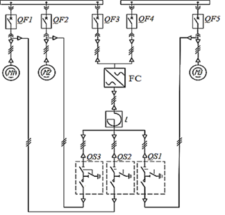
Fig. 1: Supply circuit of a group of induction motors:
QF1-QF5 – vacuum circuit breakers; FC – frequency converter; QS1-QS3 – disconnecting switches; L – reactor; M1-M3 – induction motors
To reduce these impacts, switching is realized by a special vacuum circuit breaker (for example, with the use of Toshiba Mitsubishi-Electric Industrial Systems Corporation technologies based on the TMdrive-MV inverter [1]). This solution allows switching a group of motors supplied through an inverter with further switching to a network power supply without inrush currents and overvoltages. Nevertheless, because of restricted application of that equipment, this method is not widely used.
The present paper suggests the solution of the problem by using a controlled (synchronous) vacuum circuit breaker [2,3].
Basic Principles of Controlled Switching
In comparison with common switching, controlled switching has a number of technical and economic advantages: reducing of inrush currents, elimination of dangerous switching overvoltages, lowering of the number of equipment failures, decreasing of the number of regular maintenance and increasing of life time for switching devices [4,5].
Controlled switching devices shall comply with strict requirements on stability of closing time and opening time. Scattering of operating times for these devices shall be in the range of ± (1-2) ms without dependence on load type, switching type and ambient temperatures [6].
Controlled opening is realized by contact separation at the definite instant before the moment of zero crossing for breaking current. In this case, arcing time is significantly reduced, because energy release during arcing greatly decreases. Controlling the instant of contact separation prevents circuit breaker failures and decreases influence on the power supply system [7].
Controlled closing is realized by contact closing at the definite instant after the instant of zero crossing for power supply voltage. Controlled closing of a reactive load by a circuit breaker allows minimizing inrush currents [8].
Switching Modelling for a Group of Induction Motors
Fig. 2 shows a power supply circuit for a group of induction motors. Motor starting is realized through inverters switched by a controlled vacuum circuit breaker. Switching of motors from inverter-based power supply to direct power supply is performed by opening of the controlled vacuum circuit breaker shown in Fig. 2 and closing of a group of controlled vacuum circuit breakers shown in Fig. 3.
Blocks "Inverter – Motor" are represented in Fig. 2 as space vector PWM VSI blocks.
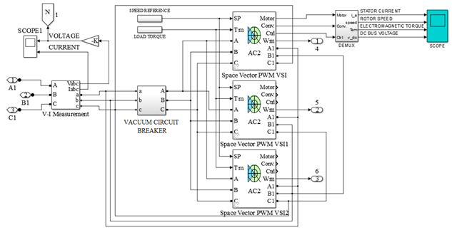
Fig.2: Modelling of a power supply system and control of a group of motors
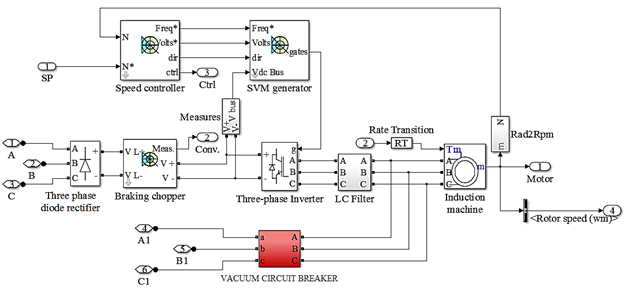
Fig.3: Block diagram of the Space Vector PWM VSI Induction Motor Drive and the vacuum circuit breaker
A block diagram for vector control of an induction motor (space vector PWM VSI) is presented in Fig. 3. The diagram includes the possibility of switching from inverter-based power supply to direct power supply from the network. The system comprises the following subsystems [8,9]: three-phase diode rectifier; the block of deceleration for a DC circuit composed of a capacitor and a resistance and switched by a thyristor (braking chopper); three-phase voltage inverter based on IGBT transistors (three-phase inverter); speed controller; space vector modulator for controlling pulse width modulation (SVM generator); induction motor; controlled (synchronous) vacuum circuit breaker.
Analysis of Modelling Results
To choose an optimal way of controlling vacuum circuit breakers, algorithms on phase rotation and time delay should be analyzed. In this case, an ungrounded electrical network is considered. Thus, we have two algorithms of controlled switching:
-simultaneous opening of two phases in the instant of equal phase voltages; then, the last phase is to be opened at voltage zero that corresponds to the time delay of 5 ms (AB-5ms-C);
- opening of the phase 'A' at voltage zero; then, after the time delay of 5 ms, the last two phases should be switched (A-5ms-BC).
As an example, the algorithm A-5ms-BC of opening a frequency converter circuit and closing induction motors with controlled voltages is analyzed. Results of modelling are shown in Fig.4, 5.
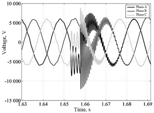
Fig. 4. Results of voltage modelling at switching to direct power supply with the A-5ms-BC algorithm
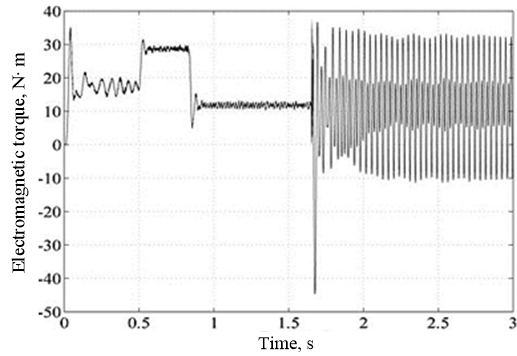
Fig. 5. Results of electromagnetic torque modelling at switching to direct power supply with the A-5ms-BC algorithm
Results of modelling show that overvoltages reduce from 3.5 times rated voltage to 2 times rated voltage, in comparison with simultaneous ABC phase switching. As for inrush torque on a motor shaft, it decreases from 5 times rated torque in the case of simultaneous ABC phase switching to 4 times rated torque in the case on controlled switching.
Results of modelling using the algorithm AB-5ms-C are presented in Fig. 6, 7.
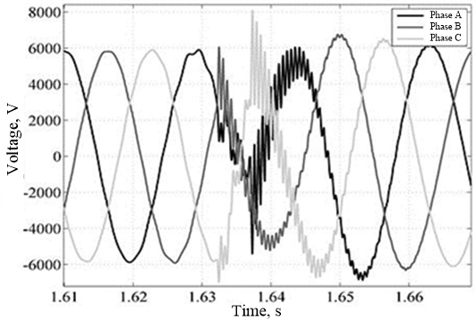
Fig. 6. Results of voltage modeling at switching to direct power supply with the AB-5ms-C algorithm
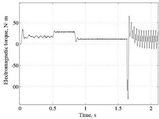
Fig. 7. Results of electromagnetic torque modelling at switching to direct power supply with the AB-5ms-C algorithm
Using this algorithm, overvoltages reduce down to 1.33 times rated voltage, while inrush torque exceeds rated torque 10 times. The last has negative influence on motor operation.
The both algorithms (AB-5ms-C, A-5ms-BC) provide overvoltage reduction in comparison with traditional switching. But the algorithm AB-5ms-C decreases inrush torques, while the algorithm A-5ms-BC increases them significantly. Therefore, these algorithms being realized do not allow simultaneous reduction of overvoltages and inrush torques to minimal values.
General recommendations on minimizing overvoltages and inrush torques state that switching shall be realized at the rated or close to the rated rotor speed, equal phase angles and equal voltages.
When rotor speed is not a rated value, which is observed in practice, it is necessary to develop an algorithm of phase synchronism search for network voltage and inverter voltage. The variant of such algorithm for one phase is given in Fig. 8. Its main principle is the following: based on the voltage-frequency ratio (Urated/frated) and an instantaneous frequency fconverter, frequency converter parameters are determined which are used for calculation of the output voltage of the frequency converter Uconverter. Providing that the converter output voltage Uconverter is equal to the network voltage Unetwork, a signal of voltage balance is generated. With the help of time delay units, it is possible to find sinusoid direction in the inverter circuit as well as in the network, i.e. by determination of the equality for sinusoidal phases. If equality conditions are fulfilled, the Boolean operator AND allows realizing switching to the operating mechanism of a circuit breaker.
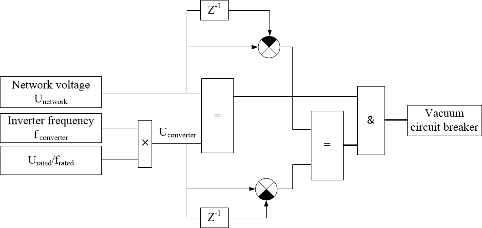
Fig. 8. Block diagram of the search algorithm for a switching instant:
Unetwork – network voltage; Urated, Uconverter – rated and actual voltage of the inverter; frated, fconverter – rated and actual frequency of the inverter; – time delay unit
The algorithm of switching from the inverter to the network is implemented by synchronization of a voltage phase angle at the inverter output with the network voltage.
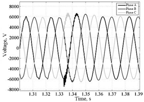
Fig. 9. Results of voltage modelling at in-phase switching to direct power supply
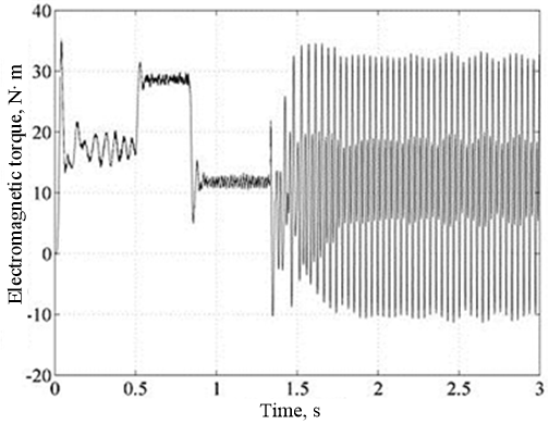
Fig. 10. Results of electromagnetic torque modelling at in-phase switching to direct power supply
Fig. 9 and 10 show voltage waveforms at the frequency converter output and torque waveforms at the motor shaft. Analysis of results reveals that the algorithm of in-phase switching allows minimizing overvoltages (down to 1.2 time rated voltage) in the vacuum circuit breaker and eliminating inrush torques at the motor shaft.
Analysis of switching algorithms allows making the following conclusion.
Being used as the main switching device, a controlled (synchronous) vacuum circuit breaker helps in reduction of overvoltages and inrush torques.
When using the A-5ms-BC algorithm, it is observed that overvoltages reduce from 3.5 times rated voltage at simultaneous ABC switching to 2 times rated voltage at controlled switching. In addition, inrush torques decrease from 5 times rated torque at simultaneous switching to 4 times rated torques at controlled switching.
The algorithm AB-5ms-C, being realized, allows overvoltage reduction down to 1.3 times rated voltage. But in this case inrush torque rises up to 10 times rated torque.
The optimal way of switching a group of motors from the inverter to the network is implementation of phase synchronism for inverter voltage and network voltage. Then, overvoltages reduce to 1.2 times rated voltage, while inrush torques are eliminated.
To develop accurate phase synchronism between the inverter voltage and the network voltage, it is recommended to use an L-C filter after the inverter. It mitigates higher harmonics generated by pulse-width modulation that allows more accurate setting of a switching phase angle.
Acknowledgements
This study was supported by the Ministry of Education and Science of the Russian Federation within the framework of the Strategic Development Program NSTU, the project C-6.
References
[1] Medium Voltage Inverter TMdrive-MV. Available at: http://www.ksgroup-nsk.ru/documents/drives/toshiba/catalog_tmdrive-mv.pdf.
[2] Prokhorenko E.V., Lebedev I.A. Investigation on Possible Development of a Vacuum Circuit Breaker for Controlled Switching of No-load Transformers. Elektro 3 (2010) 40-44.
[3] Kadomskaya K.P., LavrovYu.A., Reiherdt A.A. Overvoltages in Electrical Networks and Overvoltage Protection. Novosibirsk: Novosibirsk State Technical University, 2006.
[4] CIGRE WG 13.07. Controlled switching of HVAC circuit breakers: planning, specification and tasting of controlled switching systems. Electra: CIGRE's Bilingual Bimonthly Journal for Power System Professionals, Paris, France, 197 (2001) 23–733.
[5] Goldsworthy D., Roseburg T., Tziouvaras D., Pope J. Controlled Switching of HVAC Circuit Breakers: Application Examples and Benefits. Proceedimgs of 61st Annual Conference for Protective Relay Engineers, Texas, USA, 197 (2008) 520-535.
[6] Kleparskaya L.G. Controlled Circuit Breakers. Moscow: Energiya, 1973.
[7] D. Shevtsov, D. Pavluchenko, E. ProhorenkoThe basic principles of controlled switching and synchronous vacuum circuit breaker application in local distribution network // Applied Mechanics and Materials. - 2015. – Vol. 698 : Electrical Engineering, Energy, Mechanical Engineering, EEM 2014. – P. 743-748.
[8] German-Galkin S.G. Computer Modelling of Semi-Conductor Systems in MATLAB 6.0. Saint-Petersburg: Korona Print, 2001.
[9] Chernykh I.V. SIMULINK: environment for development of engineering models. Moscow: DIALOG-MIFI, 2003.